This post is part of a series.
I’ve decided to completely rebuild my DIY alarm system.
- Mean Well UPS supply instead of C-TEK charger
- Bigger battery in dedicated cabinet
- Arduino Mega as core, Raspberry Pi only as MQTT relay
- End-of-line resistors
The biggest change is undoubtedly moving the alarm state machine and all logic from the Raspberry Pi to an Arduino Mega. There are three main reasons for this move:
- It’s fun and I’d like to work more with the Arduino
- The Arduino Mega has 16 analog inputs, making it possible to use end-of-line resistors
- An alarm system needs to be stable — not crash, hang or get a corrupted SD card
I’ve been thinking about end-of-line resistors since I first got started, but the Raspberry Pi doesn’t have any analog inputs. Initially I thought of using the Arduino Mega as an I/O interface device, but as I got started I figured why not let it do more.
So #RPiSecuritySystem is now #DIYAlarmSystem.
Some history
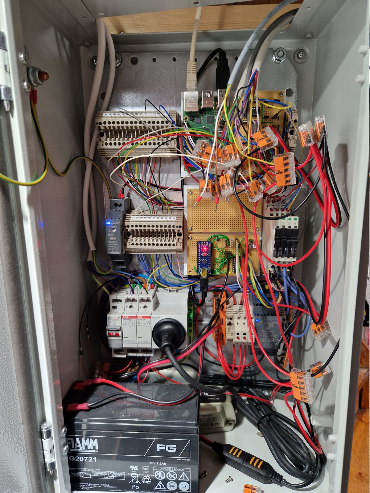
This has been the state of the alarm cabinet for a few years now — it’s crowded but it worked. The backup battery was 7.2 Ah, and the charger a CTEK MXS 3.8. It worked but there were a few problems with this solution.
The CTEK charger has different charge states; the final step is pulse, where the voltage fluctuates from 12.7 to 14.4 V. This is to see if the battery can hold its charge, if not the charge cycle is restarted. Very good for the battery, but it meant the supply voltage was fluctuating a lot.
But perhaps the biggest problem was the lack of under-voltage protection. If left running on battery for a long time, it would simply drain the battery down to nothing. Which is a terrible thing to do to a lead-acid battery.
And then there was the lack of end-of-line resistors, pretty bad for a security system. With end-of-line resistors you get defined voltage levels across the zone input — indicating if the zone is open, normal, alarmed or shorted.
Where I am now
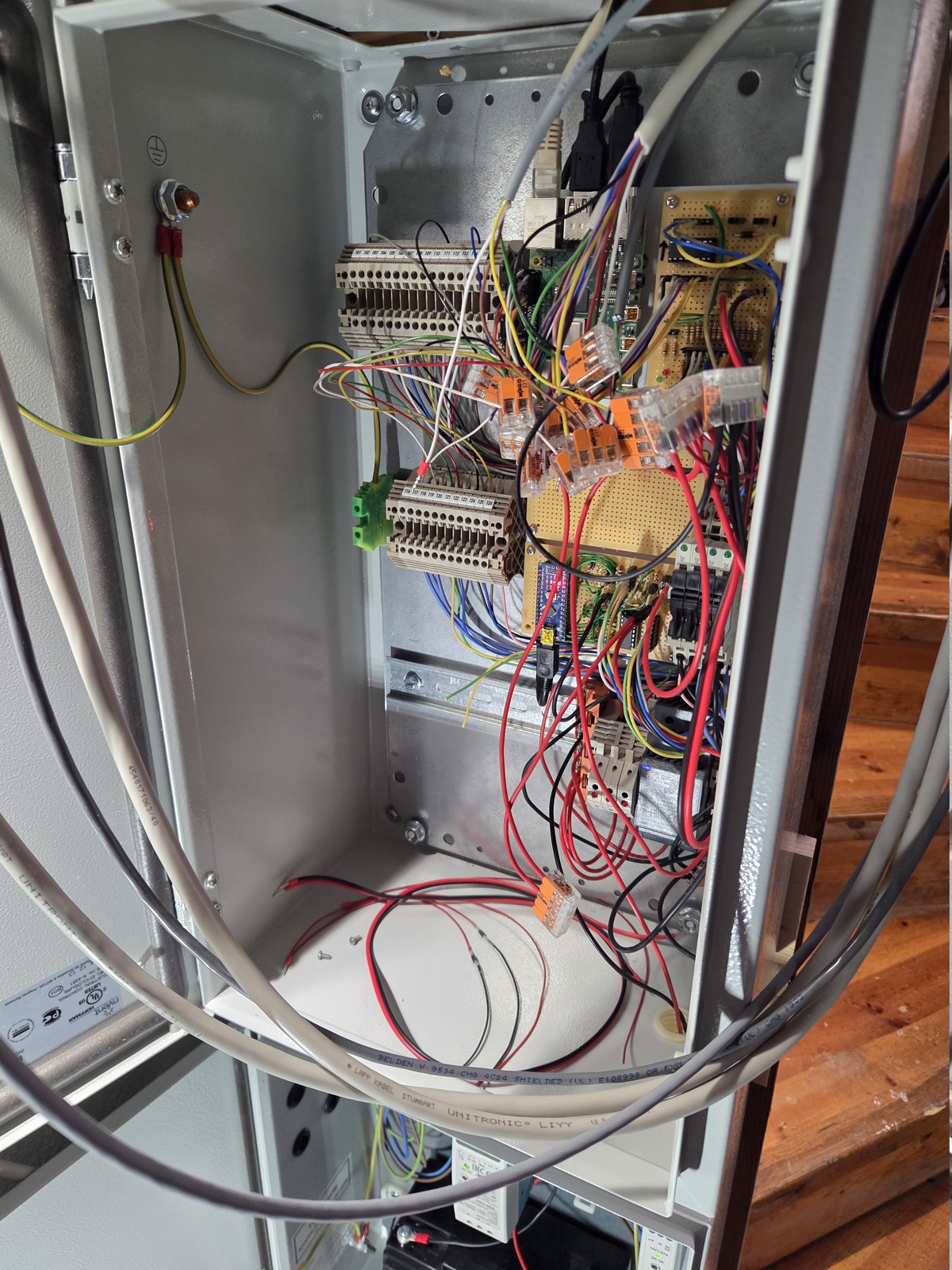
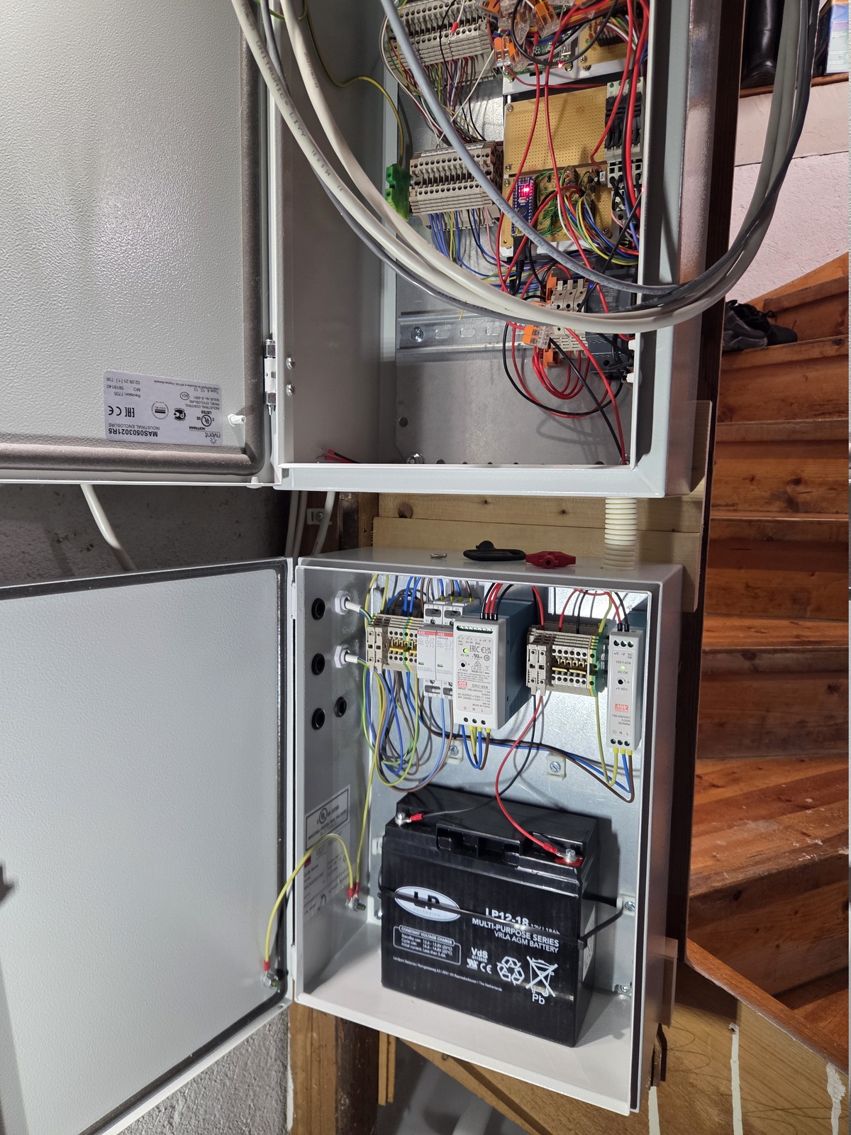
I have already mounted the power cabinet and installed new power supplies and a bigger battery.
Now I’m working on writing code for the Arduino and Raspberry Pi, and making sure they have a stable way of communicating where no messages are lost or malformed.
I’m using VS Code with Cline and DeepSeek v4 Pro to help me structure and debug. When it comes to C++ — I don’t really know what I am doing, so that has been very helpful 🤓
Most of the core features have been implemented. Next on my list is to make new I/O boards, and make room for them in the main cabinet. This probably means moving a few things around.
Power and battery
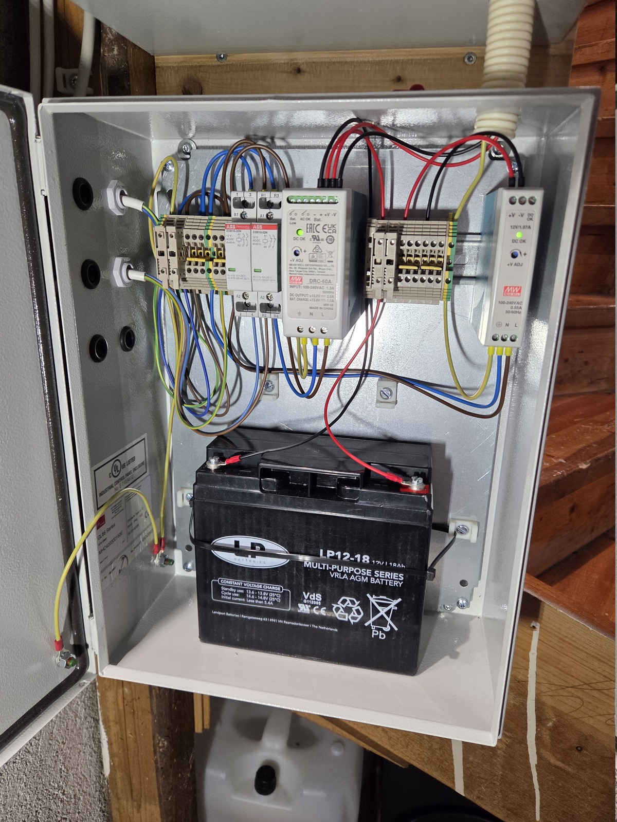
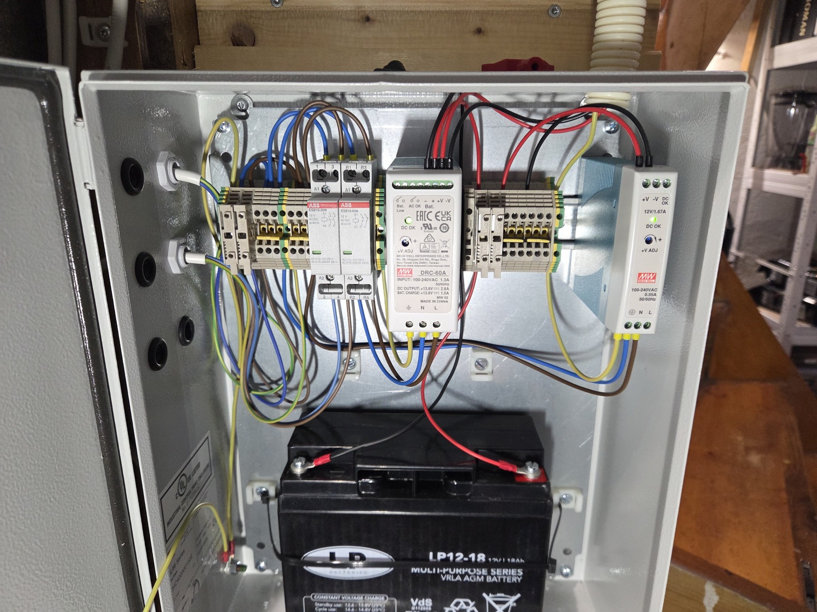
The main power supply is Mean Well DRC-60; 60 W single output with battery charger and UPS function. Nominal voltage on both is 13.8 V, the output is 2.8 A and the battery charger is 1.5 A.
The single output and charger are normally isolated, but get connected together when switching to battery power in case of mains power failure. There is a battery cut off at 10±0.5 V.
Two relays: AC OK and BATTERY LOW can inform the Arduino of the current state.
A Mean Well DDR-30G-5 DC/DC converter steps down the 13.8 V bus to 5 V (up to 6 A) for the Arduino and Raspberry Pi. This is fed from the DRC-60, providing battery backup.
The second power supply is Mean Well MDR-20-12; 20 W 12 V supply. It is used to power some control relays:
- Dishwasher cut-off
- Main water valve
- Outdoor lighting
- Main power supply cut-off (for battery testing)
I already had a 12V supply, but the MDR-20-12 has an DC OK output that I plan on using.
On the horizon
I’m studying the user manual for commercial alarm systems to get some inspiration for features and behaviour. Here are some things I am working on:
- End-of-line resistors (as already mentioned)
- Skipping exit delay when entry/exit zone is opened and closed
- Prioritize alarms based on severity (tamper, water, intruder, panic, fire)
- Part-arm, where different zones can be omitted or have different behaviour
- Area support? Not decided on this yet…
- System monitoring (voltage, temperature, tamper, etc)
- Generic output ports
- Supervisory (monitoring of external equipment)
Okay, this post is already a lot longer than I planned. There are so many things to explain that it’s hard to know where to stop, but that also makes these posts a bit challenging to write.
I just realized I haven’t explained how the system will still support both wired and wireless zones, with the Arduino as the core. But I think that is something for a future post.
I’ll stop writing now.
🖖